What is knowledge-engineering?
The process of constructing a knowledge-base in first-order logic is called as knowledge- engineering. In knowledge-engineering, someone who investigates a particular domain, learns important concept of that domain, and generates a formal representation of the objects, is known as knowledge engineer.
In this topic, we will understand the Knowledge engineering process in an electronic circuit domain, which is already familiar. This approach is mainly suitable for creating special-purpose knowledge base.
The knowledge-engineering process:
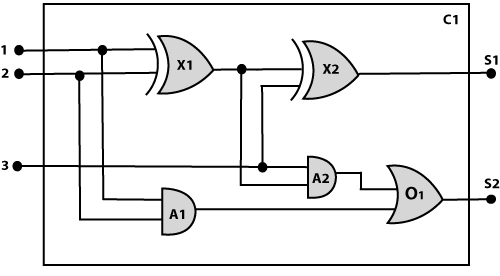
Following are some main steps of the knowledge-engineering process. Using these steps, we will develop a knowledge base which will allow us to reason about digital circuit (One-bit full adder) which is given below
1. Identify the task:
The first step of the process is to identify the task, and for the digital circuit, there are various reasoning tasks.
At the first level or highest level, we will examine the functionality of the circuit:
- Does the circuit add properly?
- What will be the output of gate A2, if all the inputs are high?
At the second level, we will examine the circuit structure details such as:
- Which gate is connected to the first input terminal?
- Does the circuit have feedback loops?
2. Assemble the relevant knowledge:
In the second step, we will assemble the relevant knowledge which is required for digital circuits. So for digital circuits, we have the following required knowledge:
- Logic circuits are made up of wires and gates.
- Signal flows through wires to the input terminal of the gate, and each gate produces the corresponding output which flows further.
- In this logic circuit, there are four types of gates used: AND, OR, XOR, and NOT.
- All these gates have one output terminal and two input terminals (except NOT gate, it has one input terminal).
3. Decide on vocabulary:
The next step of the process is to select functions, predicate, and constants to represent the circuits, terminals, signals, and gates. Firstly we will distinguish the gates from each other and from other objects. Each gate is represented as an object which is named by a constant, such as, Gate(X1). The functionality of each gate is determined by its type, which is taken as constants such as AND, OR, XOR, or NOT. Circuits will be identified by a predicate: Circuit (C1).
For the terminal, we will use predicate: Terminal(x).
For gate input, we will use the function In(1, X1) for denoting the first input terminal of the gate, and for output terminal we will use Out (1, X1).
The function Arity(c, i, j) is used to denote that circuit c has i input, j output.
The connectivity between gates can be represented by predicate Connect(Out(1, X1), In(1, X1)).
We use a unary predicate On (t), which is true if the signal at a terminal is on.
4. Encode general knowledge about the domain:
To encode the general knowledge about the logic circuit, we need some following rules:
- If two terminals are connected then they have the same input signal, it can be represented as:
- Signal at every terminal will have either value 0 or 1, it will be represented as:
- Connect predicates are commutative:
- Representation of types of gates:
- Output of AND gate will be zero if and only if any of its input is zero.
- Output of OR gate is 1 if and only if any of its input is 1:
- Output of XOR gate is 1 if and only if its inputs are different:
- Output of NOT gate is invert of its input:
- All the gates in the above circuit have two inputs and one output (except NOT gate).
- All gates are logic circuits:
5. Encode a description of the problem instance:
Now we encode problem of circuit C1, firstly we categorize the circuit and its gate components. This step is easy if ontology about the problem is already thought. This step involves the writing simple atomics sentences of instances of concepts, which is known as ontology.
For the given circuit C1, we can encode the problem instance in atomic sentences as below:
Since in the circuit there are two XOR, two AND, and one OR gate so atomic sentences for these gates will be:
And then represent the connections between all the gates.
6. Pose queries to the inference procedure and get answers:
In this step, we will find all the possible set of values of all the terminal for the adder circuit. The first query will be:
What should be the combination of input which would generate the first output of circuit C1, as 0 and a second output to be 1?
7. Debug the knowledge base:
Now we will debug the knowledge base, and this is the last step of the complete process. In this step, we will try to debug the issues of knowledge base.
In the knowledge base, we may have omitted assertions like 1 ≠ 0.
Comments
Post a Comment